
1. Background of the X-language
In recent years, Model-based Systems Engineering (MBSE) has become an important tool to support system modeling and development. Taking complex products as an example, MBSE transforms the traditional R&D mode based on documents and physical models into a model-driven R&D mode, which is a formalized description that makes MBSE reusable, non-ambiguous, easy to understand, easy to disseminate, etc., and has been widely valued by academics and enterprises. MBSE uses Systems Modeling Language (SysML) to model the whole process of a system, in order to realize the unified model-based management and optimization of the whole process of product development. Since SysML does not have the ability to describe the physical model of the product, it cannot be used for direct simulation, so it is necessary to verify the correctness and completeness of the model through other multi-disciplinary modeling and simulation methods.
A mainstream practice is to describe system components of different domains based on a unified modeling language, so as to realize seamless integration and data exchange of multi-domain models. For complex products with integrated mechanical, electrical, hydraulic, and control types, firstly, requirements modeling and architecture design are carried out based on system modeling languages (e.g., SysML, IDEF, etc.), and then physical model development and integration are realized based on physical modeling languages (e.g., Modelica, etc.) and in conjunction with the integration standards (FMI, HLA, etc.), and finally, whole-system modeling and simulation are carried out through mapping conversions between the development system models and physical models, thus realizing the different stages of product development. Finally, through the mapping conversion between the development system model and the physical model, the whole system modeling and simulation is carried out to realize the unified management of different stages of product development.
A mainstream practice is to describe system components of different domains based on a unified modeling language, so as to realize seamless integration and data exchange of multi-domain models. For complex products with integrated mechanical, electrical, hydraulic, and control types, firstly, requirements modeling and architecture design are carried out based on system modeling languages (e.g., SysML, IDEF, etc.), and then physical model development and integration are realized based on physical modeling languages (e.g., Modelica, etc.) and in conjunction with the integration standards (FMI, HLA, etc.), and finally, whole-system modeling and simulation are carried out through mapping conversions between the development system models and physical models, thus realizing the different stages of product development. Finally, through the mapping conversion between the development system model and the physical model, the whole system modeling and simulation is carried out to realize the unified management of different stages of product development.
In order to solve the above problems, this paper proposes a new generation of system-oriented integrated intelligent modeling language, which can be used throughout the whole process of architectural design, multidisciplinary modeling and simulation verification, multidisciplinary and cross-stage collaborative design modeling and simulation. At the system level, five classes, namely, definition, connection, equation, activity and state, are designed to express the structure and behavior of the system by adopting object-oriented thinking; at the model construction and simulation level, continuous models, discrete models and intelligent body models are unified under the coupled model of DEVS with the unification capability of the multi-domain model of the DEVS simulation framework, and the model and the underlying simulation are connected by the interpreter, so as to realize the system-wide specification of complex products. With the help of the interpreter, the modeling and underlying simulation can be connected, so as to realize the intelligent modeling and simulation of the whole system of complex products in a standardized and synergistic way.
2. The overall architecture of the X-language
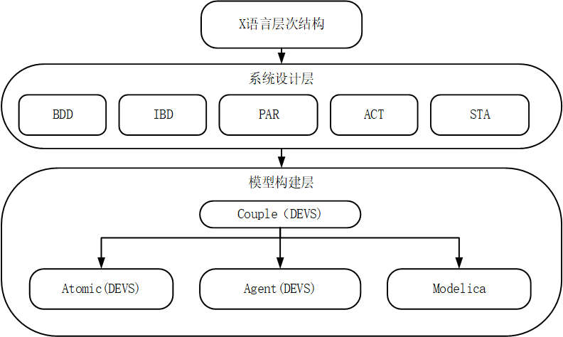
Figure 1 X language hierarchy
The description features of existing mainstream modeling languages are extracted to form the hierarchical structure of X language. As shown in Figure 1, at the system design level, five classes, namely, definition, connection, equation, activity and state, are designed to express the structure and behavior of the system by adopting the object-oriented thinking; at the model construction level, by virtue of the unification capability of DEVS simulation framework for multi-domain models, continuous models, discrete models and intelligent body models are unified under the coupled model of DEVS, which can support the description of physical behavior and simulation verification. It supports the description of physical behavior and simulation verification, and realizes the intelligent modeling of the whole system of complex products in a standardized and synergistic way. Based on this, the following modeling and simulation capabilities are given to X language:
① Supports graphical modeling and enables inter-conversion between graphics and text;
② Support the description of system-level structure and physical behavior as well as simulation and verification capabilities;
③ Support the modeling of various types of complex intelligent body models, including the learning process of intelligent body, communication process, and the parallel simulation process of multiple intelligent bodies;
④ Support continuous, discrete and mixed continuous/discrete simulation.
3. Text composition in X
Classes are the basic unit of modeling in X, and can be further divided into base classes and restricted classes. The base class is the most basic class in X and is modified by the keyword class, which contains structural and behavioral characteristics that describe any entity. X also defines a series of restricted classes, which are mainly used to more accurately describe different characteristics of the model entity and to enhance the model's ease of use and readability, and which can be replaced by class in the model without changing the model's definition. The restricted classes can be replaced by classes in the model without changing the definition of the model.
Restricted classes are modified by specific keywords including couple, continuous, discrete, agent, record, function, and connector. All classes in the X language have entities describing different characteristics as well as describing some of the components of the entity model as well as functions. The details are shown in Table 1 and Table 2.
Table 1 Descriptive capabilities of X language classes
| Class | Functions |
|---|---|
| class | Support for any model description |
| continuous | Support for descriptions of entities with continuous behavioral models |
| discrete | Support for event-based triggering of descriptions of behavioral model entities |
| agent | Support for descriptions with intelligent behavioral model entities |
| couple | Supports the description of system-level models with multiple components |
| record | Support for the description of complex data structures in various model entities |
| function | Description of algorithms required to support process-based modeling for various types of model solutions |
| connector | Support for various types of models having descriptions that follow Kirchhoff's law connectors |
Table 2 Architectural composition of the two modeling forms of the X language class
| class | Different classes of graphic modeling compositions | Different classes of text modeling compositions |
|---|---|---|
| class | Definition diagrams, connection diagrams, equation diagrams, state machine diagrams, activity diagrams | Definition section, Connection section, Equation section, State section, Activity section |
| continuous | Definitional diagrams, equation diagrams | Definition section, equation section |
| discrete | Definition diagrams, state machine diagrams | Definition section, state section |
| agent | Definition charts, activity charts | Definition section, activity section |
| couple | Definition diagrams, connection diagrams | Definition section, connection section |
| record | definition graph | definition section |
| function | Definition charts, activity charts | Definition section, activity section |
| connector | definition graph | definition section |
The contained elements and syntactic structure of each class are specified below.
1)Continuous module
Continuous classes are defined for entities with continuous behavior. The behavior of entities with continuous behavior changes over time and can be described by mathematical equations. The structural properties of entities with continuous behavior include the definition of parameters and their types to be instantiated, the definition of state variables, and the definition of ports; the behavioral properties can be defined based on mathematical equations. Based on this, continuous classes in X language are described by definition diagram and definition part, and equation diagram and equation part to describe their structural properties, and behavioral properties in graphical and textual modeling respectively. The details are shown in Table 3.
Table 3 Continuous class definitions
| contiguous category | Continuous class properties | use |
|---|---|---|
| Definition map/definition section | parameter | Instantiation parameters and their type definitions are required |
| value | State Variable Definitions | |
| port | Port Definition | |
| Equation graphs/part of equation | equation | Definition of behavior described by mathematical equations |
2)Discrete module
Discrete classes are defined for discrete models. The behavior of a discrete model is event-based and can be abstracted by defining its state. The structural properties of a discrete model generally include the parameters to be instantiated and their types, state variables, and the definition of ports; the behavioral properties are defined based on state machine theory. Based on this, the discrete classes in X language are modeled in graphical and textual modeling by defining their structural properties through definition diagrams and definition sections, and their behavioral properties through equation diagrams and equation sections. The details are shown in Table 4.
Table 4 Discrete class definitions
| discrete class | Discrete class properties | use |
|---|---|---|
| Definition map/definition section | parameter | Instantiation parameters and their type definitions are required |
| value | State Variable Definitions | |
| port | Port Definition | |
| State machine diagram/state section | state | Behavioral definitions described in terms of state machines |
3)Couple module
Coupling classes are defined for coupling models. The coupling class was designed to give the X language the ability to describe system-level entity models, which centers on describing the components contained in a system-level entity and the connections between them. Based on this, the coupling class in X language describes the system components in the graphical and textual modeling through the definition diagram and definition section, and describes the component connections through the connection diagram and connection section, respectively. The details are shown in Table 5.
Table 5 Coupling class definitions
| coupling class | Coupled Class Attributes | use |
|---|---|---|
| Definition map/definition section | reference | Calling other modules |
| part | Component Definition | |
| Connection diagram/connection section | connection | Component Connection Relationship Definition |
4)Agent module
The design of intelligence classes in X follows the BDI architecture, but in a more concise way. The core content of goal guiding the execution of the plan is retained, while a series of content such as environment perception is left to be defined by the user to enhance the extensibility of the language. When modeling with the Agent class, the whole structure can be divided into two parts, namely the definition part and the action part, where the definition part is used to initialize the values of parameters and variables, as well as the declarations of functions and plans, and the action part is used to control the execution of the plan and set the start and end conditions for the simulation of the intelligent body. The action part is used to control the execution of the plan and set the start and termination conditions of the intelligent body simulation.
The plan corresponds to the Intention part of the BDI architecture, the content defined in the Execution part corresponds to the goal part, and the Belief part is integrated into the process of the whole intelligent body interacting with the environment and sensing. On the basis of retaining the characteristics of the original BDI architecture, it is integrated with the syntax and semantics of the X language to give the X language intelligent characteristics.
Table 6 Definition of intelligent body classes
| class of integers | Attributes of Smart Body Classes | use |
|---|---|---|
| Definition map/definition section | parameter | Instantiation parameters and their type definitions are required |
| value | State Variable Definitions | |
| reference | Calling other modules | |
| plan | Intelligent Body Behavioral Sequence Definition | |
| Activity map/activity section | active | Program execution logic definition |
Intelligent body classes are defined for intelligent body models, which generally have behaviors to communicate and interact with other entities. Based on this, the intelligent body class in X language describes the behavioral characteristics in graphical and textual modeling by defining the structural characteristics of graphs and definition parts, and the behavioral characteristics of activity graphs and activity parts, respectively. The details are shown in Table 6.
5)record module
Record classes are defined for the purpose of facilitating the modeling of entities with different data types. For this reason, the record classes in the X language describe the types of data included in graphical and textual modeling through definition diagrams and definition sections. The details are shown in Table 7:
Table 7 Record class definitions
| record class | Record Class Attributes | use |
|---|---|---|
| Definition map/definition section | value | Definition of different data types |
6)function module
Function classes are defined for the purpose of modeling entities with complex functional behavior. Functions include input and output parameters as well as implementation definitions. Based on this, the function classes in X language are modeled in graphical and textual ways by means of definition diagrams and definition sections describing their input and output parameters, and activity diagrams and activity sections describing their specific functional implementation processes. The details are shown in Table 8:
Table 8 Function Class Definitions
| function class | Function Class Attributes | use |
|---|---|---|
| Definition map/definition section | value | Input/output parameter definitions |
| Activity map/activity section | active | Functional realization process definition |
7)connector module
The Connector class is defined for entity models that have connectors that follow Kirchhoff's laws. The type of data transferred between entities and other entities is defined in the connector. Based on this, the connector class in the X language describes the type of data transferred during graphical and textual modeling by defining diagrams and definition sections as shown in Table 9:
Table 9 Connection class definitions
| connector class | Connector Class Properties | use |
|---|---|---|
| Definition map/definition section | value | Input/Output Data Type Definitions |
4. Interpreter architecture for the X language
X is an object-oriented multidomain system modeling language, which not only includes the characteristics of object-oriented languages, but also encompasses the characteristics of equation-based modeling languages, and the two are generally not the same in the interpretation of the routes, so the interpretation of X needs to adopt different technical routes.
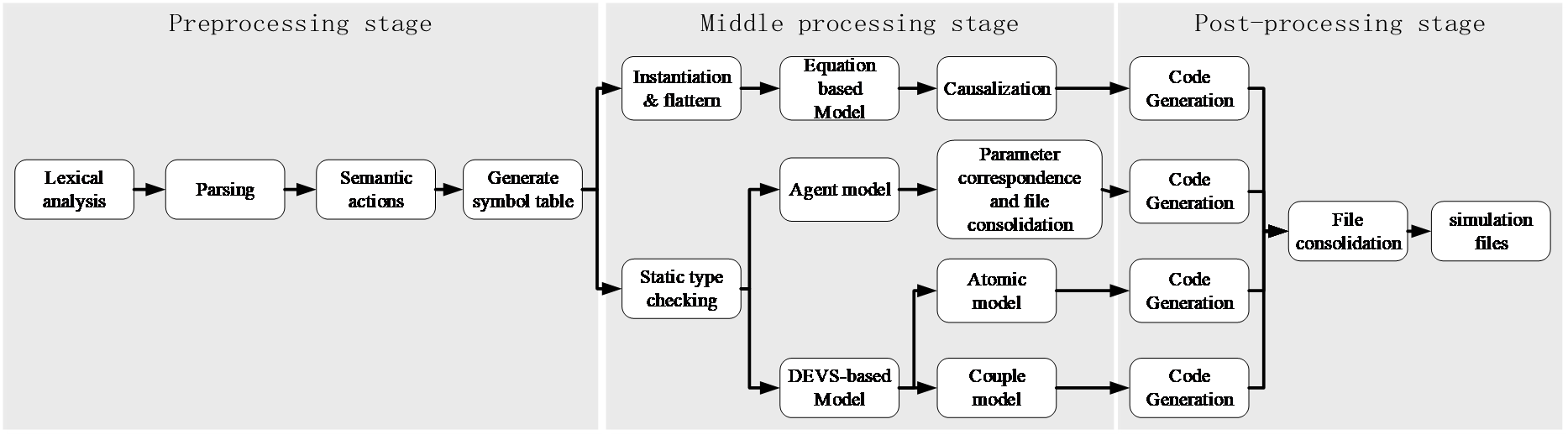
Figure 2 X language interpreter framework
The interpretation process is divided into three phases, which are pre-processing phase, intermediate processing phase and post-processing phase.
The preprocessing phase, which is not explicitly different from the two approaches described above, is responsible for lexical and syntactic analysis of the source code to obtain an abstract syntax tree, and for collecting information about the elements in the model to create a symbol table.
The intermediate processing stage uses different techniques depending on the type of model included in the interpreted file, and for continuous models based on equations, they are first flattened to obtain a flattened system of equations. The system of equations is then transformed in the factorization stage into a form suitable for solving by a differential equation solver. For assignment-based models, i.e., intelligent body models and models based on the DEVS specification, the static type checking of each statement contained in the model is first carried out with the help of the symbol table constructed in the previous stage, and then different techniques are chosen according to the different types of models. The reason for adopting different interpretation routes is that the interpretation and code generation of DEVS model can correspond to the simulation code, while the upper layer model representation of the intelligent body model is farther away from the bottom layer, and needs to go through the correspondence of parameters and the integration of the generated files in order to make sure that the necessary information will not be lost, so that the complexity of the operations required by the two models is not the same. After the intermediate phase, all data structures required for model simulation have been processed.
In the last stage, the processed data structures from the three technology paths are traversed and the respective model simulation files are obtained, and if there is a hierarchical structure in the model, the file hierarchies need to be integrated in order to obtain a simulation file for the whole model.
5. X-language emulator architecture
The ability of the X language to model multiple domains requires that it be able to simulate multi-disciplinary models. DEVS, as a framework that supports multi-domain modeling, is well suited to meet the needs of the X language, providing support for the simulation and verification of multi-domain models.
The most efficient implementation of the DEVS simulation algorithm is the hierarchical recursive program developed by Zeigler et al. As shown in Fig. 5, for the DEVS simulation structure, each atomic model corresponds to a simulator in the simulator, which executes the internal and external events of that atomic model; the coupled model corresponds to a coordinator, which is responsible for scheduling the events of the atomic models inside the model. The coupled model corresponds to the coordinator, which is responsible for scheduling the events of the atomic model inside the model. At the top level of the whole model, it corresponds to the root-coordinator, which manages the advancement of events for the whole model.
In X, the architecture of the DEVS emulator is maintained, with some extensions for language specificities:
1) First, the continuous model exists as an atomic model in the simulator, which is based on the expansion of the continuous model by DEV & DEVS. The state events and time events defined in the continuous model are further abstracted as internal events of the atomic model in the framework, and the equations are solved at the time nodes triggered by the internal and external events.
2)The intelligent body model exists as a coupled model, but according to the DEVS theory, the coupled model can be regarded as a special atomic model, so it is treated as an atomic model in the simulator structure.The intelligent body model of X-language is realized based on the BDI architecture, which divides the intelligent body model into four modules, namely goal, schedule, plan and interaction. In the design, it can interact with other atom models or intelligent body models based on interaction.
3)By expressing the intelligent body and continuous model as DEVS model through the above two points, the connection among intelligent body, discrete and continuous models is abstracted as event-based connection, which can support the modeling and simulation of multi-domain models.
Throughout the X language simulator, the connected simulator and coordinator communicate with each other based on messages. Each time an event occurs (internal or external), the coordinator sends a transition message to its children to notify them to perform the transition, and the simulator computes its next state when it performs an internal or external event, and sends the output to its parent coordinator if it performs an internal transition. Therefore, there are three types of communication between the simulator and the coordinator, as shown in Figure 1, namely internal and external event notifications from the coordinator to the simulator and outputs from the simulator to the coordinator.
Each simulator and coordinator defines the time at which the next internal transition occurs. In the simulator, this time is calculated by the time advance function of the atomic model. In the coordinator, the next event occurs by getting the next event times of all child nodes and taking the minimum value as its own next event time. Therefore, the next event time of the root-coordinator is the minimum of the next event times of all models in the system. the root-coordinator continuously advances the global time t to its corresponding event time, sends an event message to its children to notify them to execute the event. This cycle is repeated until the end of the simulation.
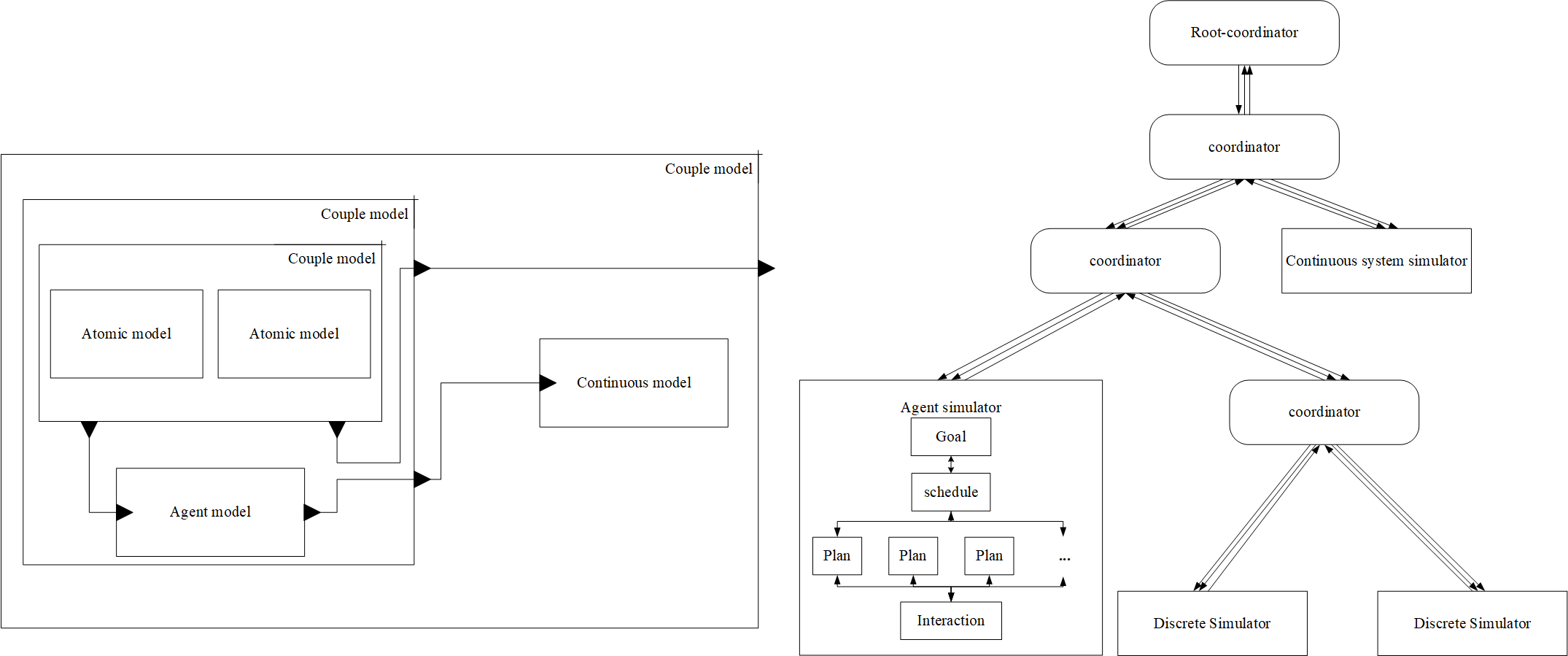 a. Model Hierarchy
b. Simulator Hierarchy
a. Model Hierarchy
b. Simulator Hierarchy
Fig. 3 Emulator structure
Video for the X language